Radon Mitigation System Diagram: Slab to Roof, Explained
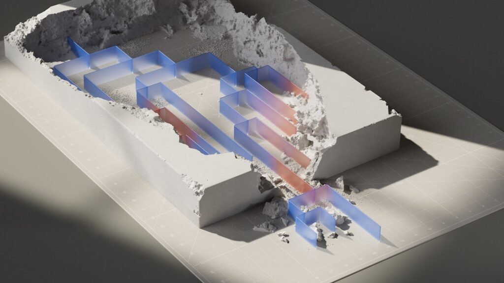
Most homeowners first meet a radon mitigation system as a white pipe in the basement and a fan somewhere outside or in the attic, with little sense of how the pieces connect. A radon mitigation system diagram fills that gap. It traces the path soil gas takes from beneath the foundation, through a sealed pipe, past a gauge and a fan, and out above the roofline. This guide builds that diagram in words, one component at a time from slab to roof, then shows how the layout changes for homes with a sump pit or a dirt-floor crawlspace. It quotes EPA’s own placement rules for the fan and the exhaust so that a homeowner can compare the drawing with the real thing. It summarizes EPA and CDC guidance current as of 2026 and is educational only; design and repairs belong with a qualified radon mitigator, and health questions belong with a physician.
Part of our Radon Mitigation Systems guide — start there for the full picture →
What a Radon Mitigation System Diagram Shows
A typical diagram shows active subslab suction, also called subslab depressurization. EPA’s Consumer’s Guide to Radon Reduction calls it the most common and usually the most reliable radon reduction method. In EPA’s description, one or more suction pipes are inserted through the floor slab into the crushed rock or soil underneath, and a radon vent fan connected to the pipes draws radon from below the home and releases it into the outdoor air while creating a negative pressure, or vacuum, beneath the slab.
That last idea is the heart of every diagram. Radon is a gas released from rocks, soil and water, and CDC notes that it can get into homes through small cracks or holes. EPA explains that air pressure inside a home is usually lower than pressure in the soil around the foundation, so the house tends to draw soil gas in. The mitigation system flips that relationship under the slab: the fan makes the space under the floor lower in pressure than the room above, so gas moves into the pipe instead of up through the floor.
The mitigation illustration in EPA’s Citizen’s Guide to Radon carries a useful caveat: it is “a composite view of several mitigation options,” and “the typical mitigation system usually has only one pipe penetration.” So a real house rarely looks as busy as a textbook drawing. The sub-slab radon mitigation system guide expands on the method itself.
The Diagram in Words: Slab to Roof
Read this list from the bottom of the house to the top. Each step is one piece of the drawing.
- Gravel or soil beneath the slab. The starting point is the layer under the concrete. EPA notes that the number and location of suction pipes depends on how easily air can move in the crushed rock or soil under the slab and on the strength of the radon source, and that often only a single suction point is needed. Loose gravel lets suction spread widely; tight clay or sand limits it.
- The suction pit. Installers commonly core a hole through the slab and dig out a small cavity of material beneath it. The cavity gives the pipe an open space to draw from and helps the vacuum spread outward. Its size varies with the soil and the installer’s judgment.
- The PVC suction pipe. A plastic pipe, usually 3 or 4 inches in diameter in residential work, rises out of the hole. In a basement this is the white pipe people notice first. The radon pipe in basement guide covers living with it day to day.
- The slab seal. The gap around the pipe where it passes through the concrete is sealed, typically with urethane caulk or a similar sealant, and visible cracks and floor-wall joints are often sealed too. EPA says sealing limits the flow of radon into the home and makes other techniques more effective and cost-efficient, but does not recommend sealing alone.
- The manometer or warning device. A small gauge mounted on the pipe at eye level shows whether the fan is pulling. EPA requires a warning device on active systems and lists examples: a liquid gauge, a sound alarm, a light indicator, and a dial or needle display gauge. The manometer gauge guide explains how to read it.
- The system label. Somewhere on the visible pipe is a label identifying the system. EPA states that radon reduction systems must be clearly labeled to avoid accidental changes that could disrupt the system.
- The pipe route. From the gauge, the pipe runs either up through the house, in a closet or chase, to the attic, or out through a rim joist or wall to the exterior. Runs are usually sloped so condensation drains back toward the suction pit.
- The fan. The fan sits along the route in an unconditioned space, such as an attic or garage, or outside on an exterior wall. Everything below the fan is under suction. Everything above it is under slight positive pressure, which is why its location matters so much.
- The discharge. The pipe ends above the roof edge, open to the air or under a cap designed for the purpose, where EPA says the gas is quickly diluted.
| Component | Location | Purpose |
|---|---|---|
| Gravel or soil layer | Beneath the slab | Medium the vacuum spreads through |
| Suction pit | Directly under the slab penetration | Open cavity that helps extend the suction field |
| PVC suction pipe | From the slab up through the house or out a wall | Carries soil gas away from the foundation |
| Slab and crack seals | Around the pipe and at cracks or joints | Limits leakage so the vacuum holds |
| Manometer or warning device | On the pipe, where it can be seen or heard | Shows or signals whether the system is working |
| System label | On visible pipe sections | Prevents accidental changes |
| Radon fan | Attic, garage or exterior, never in or below living space | Creates the suction that drives the system |
| Discharge outlet | Above the roof surface, clear of openings | Releases gas where it dilutes outdoors |
| Sump lid (if present) | Over the sump pit | Seals the pit so it can serve as a suction point |
| Membrane (crawlspaces) | Over the exposed earth floor | Creates a sealed space for submembrane suction |
EPA’s Rules for Fan Location and Discharge
Two parts of the diagram are governed by specific language in EPA’s Consumer’s Guide, in its checklist for checking a contractor’s work. They are worth reading exactly as written, because they explain why systems are routed the way they are.
Where the fan can go
“The exhaust fan must not be located in or below a livable area. For instance, it should be installed in unconditioned space.”
Elsewhere in the same guide, EPA lists common fan locations as “unconditioned home and garage spaces, including attics and the exterior of the home.” It also says that if a fan is installed outside, the contractor must install a fan that meets local building codes for exterior use, and that electrical connections must follow local electrical codes. In a diagram, this is why the fan is drawn above the living space, in the attic or garage, or on the outside wall, and never in a finished basement. The radon fans guide covers fan types and sizing, and the exterior radon fan guide covers outdoor mounting.
Where the exhaust must end
“The exhaust pipes of soil suction systems must vent above the surface of the roof and 10 feet or more above the ground, and must be at least 10 feet away from windows, doors or other openings that could allow radon to reenter the home, if the exhaust pipes do not vent at least 2 feet above these openings.”
In a drawing, that rule is why the pipe extends above the roof line rather than ending at a side wall near a window. Additions, dormers, decks and new windows can create conflicts years later, so it is worth checking the discharge against this sentence after any exterior work. The radon exhaust system guide looks at discharge layouts in more detail.
Running continuously
One more line from the same guide belongs on any diagram legend: “the fan should NEVER be turned off; it must run continuously for the system to work correctly.”
Pressure Field Extension: The Part a Diagram Cannot Draw
Diagrams usually show a few arrows under the slab pointing toward the pipe. Those arrows represent what mitigators call pressure field extension: how far the vacuum created at the suction pit reaches across the underside of the slab. A system works well when that field covers the whole footprint, so that soil gas everywhere under the house is pulled toward the pipe rather than into the rooms.
EPA does not use that phrase in the Consumer’s Guide, but it describes the diagnostic behind it. A soil communication test, according to EPA, uses a vacuum cleaner and chemical smoke to determine how easily air can move from one point to another under the foundation. A contractor applies suction at one small hole and watches whether smoke at a second hole is pulled downward. Professionals may also use a micromanometer to measure small pressure differences at test holes, though methods vary by contractor and by state requirements.
In practical terms, pressure field extension is why some houses need one suction point and others need two or more. Gravel beds under newer slabs often spread suction easily. Older homes with dense soil, multiple slab levels, or separate additions may need extra points or a stronger fan. EPA notes that whether diagnostic tests are needed depends on the foundation design, the material under the home, and the contractor’s experience with similar homes. This is also the main reason two systems that look identical in a drawing can cost very different amounts; the radon mitigation systems cost guide breaks that down.
Variant Diagrams: Sump, Drain Tile, Block Wall and Crawlspace
Not every house has a simple slab over gravel. EPA’s Consumer’s Guide describes several variants, and each changes the bottom of the diagram while the top, from fan to roof, stays much the same.
Sump-hole suction
EPA describes sump-hole suction as a variation of subslab and drain tile suction: when a basement has a sump pump, “the sump can be capped so that it can continue to drain water and serve as the location for a radon suction pipe.” In a diagram, the suction pipe rises from a sealed lid over the pit rather than from a cored hole. Pump cords and discharge lines pass through sealed grommets. EPA’s comparison table notes that sump-hole suction works best if air moves easily to the sump from under the slab. The radon sump pump cover guide shows what a sealed lid involves.
Drain tile suction
Some homes have drain tiles or perforated pipe that direct water away from the foundation. EPA says suction on these tiles or pipes is often effective. A diagram would show the radon pipe tied into that perforated loop, using it to spread suction around the perimeter.
Block-wall suction
Homes with hollow block foundation walls can use block-wall suction, which EPA says removes radon and depressurizes the block wall, and is often used in combination with subslab suction. The drawing adds a pipe connection into the wall cavities, with openings in the blocks sealed.
Crawlspace submembrane suction
For crawlspaces with an earth floor, EPA describes covering the ground with a high-density plastic sheet, then using a vent pipe and fan to draw radon from under the sheet and vent it outdoors. EPA calls this submembrane suction and says that, when properly applied, it is the most effective way to reduce radon in crawlspace homes. A diagram shows the membrane sealed at seams and to the foundation walls, with a suction connection beneath it, often linked to perforated pipe laid on the soil. EPA describes active crawlspace depressurization, which draws air directly from the crawlspace, as a less favorable option that generally does not work as well and needs attention to combustion appliance backdrafting and to sealing the crawlspace off from the rest of the home.
Mixed foundations
Many Front Range homes combine a basement with a crawlspace or a slab-on-grade addition. EPA notes that homes may have a basement under part of the home and a slab or crawlspace under the rest. Diagrams for these houses often show two suction branches joining into one pipe before the fan.
Interior Versus Exterior Pipe Routes
The middle section of a diagram, between the gauge and the fan, is where real systems differ most. Two layouts cover most homes.
Interior route
In an interior route, the pipe rises from the basement through a closet, utility chase or wall cavity into the attic. The fan sits in the attic, which is unconditioned space, and the discharge passes through the roof. From outside, the only visible part may be a short pipe stub above the shingles. Interior routes keep the pipe out of sight and away from weather, and the fan is protected from sun, wind and snow. The trade-offs are more framing work during installation and a fan that is harder to reach for service.
Exterior route
In an exterior route, the pipe leaves the basement through the rim joist or foundation wall, and the fan mounts on the outside wall. A vertical pipe then runs up the side of the house and continues above the roof edge. This layout is often simpler to install and makes the fan easy to reach, but the fan and pipe are exposed to the elements. EPA requires an exterior fan to meet local building codes for exterior use. In cold climates such as the Colorado Front Range, exterior runs may be more prone to condensation freezing near the outlet during long cold spells, so installers often pay close attention to pipe slope and outlet design; local practice varies.
Garage routes
A third option sends the pipe into an attached garage, with the fan mounted in the garage or garage attic and the discharge through the garage roof. EPA’s list of common fan locations specifically includes garage spaces. In a diagram, the pipe crosses a shared wall before rising.
All three routes have to satisfy the same rules at the top: the fan outside living space and the discharge above the roof surface, clear of openings. Which route suits a house depends on its layout, appearance preferences and access, and a mitigator usually discusses the options before work begins.
Passive Systems and Radon-Ready Homes
Some newer homes have a pipe from the slab to the roof but no fan. These are passive systems. EPA’s Consumer’s Guide explains that passive subslab suction relies on natural pressure differentials and air currents instead of a fan, is usually associated with radon-resistant features in newly built homes, and is generally not as effective at reducing high radon levels as active suction. The Citizen’s Guide adds that every new home should be tested after occupancy, even if it was built radon-resistant, and that if levels are still above 4 pCi/L, the passive system should be activated by having a qualified mitigator install a vent fan. In a diagram, a passive system looks like the active version with the fan missing, and often with space left in the attic where one can be added.
Using the Diagram to Check a Real System
A diagram is most useful as a checklist. Walking the system from bottom to top, a homeowner can confirm each piece without tools:
- Is the slab penetration sealed, and is the sump lid, if any, bolted and gasketed?
- Is there a gauge or alarm, and is it where it can be seen or heard easily, as EPA requires?
- Is the system labeled?
- Is the fan outside the living space, in an attic, garage or on an exterior wall?
- Does the discharge rise above the roof surface and stay clear of windows and doors as EPA’s rule describes?
A diagram cannot confirm that radon is actually low. EPA recommends a post-mitigation test within 30 days of installation, but no sooner than 24 hours after the fan is running, and suggests retesting at least every two years. CDC advises testing again after any repairs. CDC also states that there is no known safe level of radon and that EPA recommends fixing a home at 4 pCi/L or higher. For new installs, the radon fan installation guide covers what happens on install day, and the radon mitigation system maintenance guide covers upkeep afterward. The radon mitigation hub groups every system guide in one place, and the radon testing pillar starts from the beginning with testing.
Finally, EPA’s Consumer’s Guide suggests asking the contractor to fully explain the system, demonstrate how it operates and provide written operating and maintenance instructions. A simple sketch of the house’s own system, with the suction point, pipe route, fan location and discharge marked, is a reasonable thing to request and a useful document to pass on at resale.
References
- U.S. EPA. Consumer’s Guide to Radon Reduction: How to Fix Your Home (PDF, 2016)
- U.S. EPA. A Citizen’s Guide to Radon (PDF, 2016)
- CDC. Radon and Your Health
Frequently asked questions
What are the main parts of a radon mitigation system?
A typical active subslab system has a suction point under the slab, a sealed PVC pipe, a manometer or other warning device, a system label, a fan in unconditioned space or outdoors, and a discharge above the roof.
Why is the radon fan never in the basement?
EPA's Consumer's Guide states the exhaust fan must not be located in or below a livable area and should be installed in unconditioned space. Common locations are attics, garages and exterior walls.
How high does a radon vent pipe need to go?
EPA says soil suction exhaust pipes must vent above the surface of the roof and 10 feet or more above the ground, and at least 10 feet from windows, doors or other openings unless they vent at least 2 feet above them.
How does a crawlspace radon system differ from a basement system?
In a crawlspace, the earth floor is covered with a high-density plastic sheet and the fan draws radon from under that sheet. EPA calls this submembrane suction and describes it as the most effective approach for crawlspace homes when properly applied.
Does a radon system need more than one suction point?
Often one is enough, according to EPA. Homes with dense soil, several slab levels or mixed foundations may need more, which a mitigator usually decides through diagnostic testing.
Trying to match the system in a house to a diagram, or unsure whether the fan and discharge meet EPA’s rules? Reach out to our team with a few photos and we can help interpret the setup.
Radon mitigation fans & parts
If a sub-slab depressurization system is the fix, the inline fan is the heart of it. Match the fan to your soil and pipe diameter — or have a certified installer size it.
| Product | Why | Buy |
|---|---|---|
 RadonAway RP145 Inline Fan RadonAway RP145 Inline Fan | Common 4-in. SSD workhorse fan. | Amazon — $152.00 |
 Fantech Rn2 Radon Fan Fantech Rn2 Radon Fan | Quiet operation; energy-efficient. | Amazon — $153.89 |
 Radon U-Tube Manometer Radon U-Tube Manometer | Confirms the system is pulling suction. | Amazon — $8.95 |